Installing, Securing and Testing the 4.5 kwh 21s Lithium NMC Battery Pack and BMS into the Bike.
- evconversionrider
- Mar 19
- 4 min read
I believe the most challenging aspect of the build has been installing the batteries. If any part of this installation is not done properly and cautiously, it could lead to damage to the pack or, in the worst case, a fire.
The initial step of the installation involves ensuring that the batteries do not touch the Aluminium Enclosure. Since we are handling charged batteries, it is crucial to exercise extreme caution to prevent the battery terminals from short-circuiting on any metal components or tools.
The outer casing of Lithium NMC Batteries is covered with a thin plastic layer. If this layer becomes damaged or scratched, it can cause a short circuit with the enclosure or another battery. Since the outer casing is connected to the battery's positive terminal, placing two batteries side by side in series can lead to a short circuit if the insulation between them fails.
To avoid the batteries short-circuiting against the enclosure or another battery, we will line the enclosure with rubber and insert a thin HDPE sheet between each battery.
The initial step involves lining the enclosure with high-density rubber to prevent the batteries from touching the aluminium. Additionally, we will pack the sides with high-density foam to ensure a snug fit for the batteries, allowing for some expansion as well as minimising any movement that could lead to the loosening of the battery terminals.
While lining the Enclosure with rubber for the bottom row of batteries, I observed some lumps on the weld that could potentially damage the rubber and allow the battery to come into contact with the Aluminium Enclosure, as illustrated below.


This video demonstrates the importance of taking your time to properly line the enclosure before installing the batteries.
This led to me needing to install the batteries several times to ensure their safety. Once I was confident that the batteries were protected from any damage, they were placed into the lower section of the enclosure.
With the bottom row of batteries securely positioned, we must now test fit the top row, to ensure the batteries fit correctly and the spacing block supporting the top row over the bottom row are level for the correct fit.
Having confirmed that the batteries fit securely and will keep the pack safe, we now need to explore our options for linking the batteries and connecting the BMS wires to each battery.
The simplest approach is to place the lug for the BMS wire directly on the positive terminal, positioning it between the nut and the copper link.
My issue with this option is that the underside of the nut is grooved to grip the copper link when tightened. If the lug is placed under the nut, it will function like a washer and prevent the nut from securing against the link.
To guarantee a secure connection between the battery and the link, I decided to include an extra 5mm terminal on the link for connecting the BMS wire.

With the link organised, we can now install the BMS and start connecting the bottom row of batteries.
First, we need to install the battery links between the batteries directly beneath the BMS to properly tighten the battery terminals to 6 nm. The suggested tension for the battery terminals is between 5 and 7 nm.
Now that the BMS is firmly attached to the HDPE board, we can place the BMS at the front of the battery pack. The board to which the BMS is attached will press down on the bottom row of batteries, helping to secure them once the enclosure lid is fastened.
We will now need to label all of the BMS Battery connections for each batteries as once the BMS is fitted, it will be impossible to trace the wires back to the BMS.
After positioning the BMS and connecting the B- to Battery number 1, we will proceed through the pack, connecting all the batteries according to the Wiring Diagram I sourced from Globelpower.com.


Once the connections to all batteries have been verified, we can activate the BMS using the BMS screen and view the readings through the BMS app.


By using the app to access the BMS controls, I will deactivate the Discharge Function in the app to guarantee the pack's safety while connecting the Positive output cable to the battery pack.
With the battery pack and BMS confirmed to be connected and functioning properly, I can start securing all the BMS cables and begin installing the HDPE and rubber spacers to prevent any battery movement within the pack once the lid is fastened.
For the bottom row of batteries, I have protected the battery terminals with HD Rubber and placed the BMS cable on top of the rubber to prevent any damage to the BMS wires from the battery terminals.

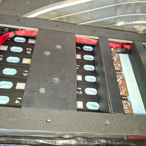
Proceeding to the top row of batteries, the initial task is to install the HDPE boards. These boards will prevent the top row from moving forward and, along with the packing blocks placed on top, will secure both the top and bottom rows of batteries in place.


We now need to create and install the retaining blocks that will fit between the batteries, terminals, and the enclosure lid to secure the battery pack.
Now, I'll show you some photos of the completed product, which we've test-fitted to verify that the pressure is correct and uniform across the pack. I used high-density foam for the box seal because it compresses more easily than rubber. This ensures that the enclosure lid applies the necessary pressure to secure the batteries within the pack, minimising movement and thereby reducing the risk of loose terminals.


After successfully installing the battery packing support, the last step is to connect the main positive cable from the positive battery terminal to the Main Fuse situated on top of the lid.
In this video, to prevent any accidents, I have taped the nearby terminal to avoid sparks that could occur if a nut or washer falls between the terminals while connecting the main positive cable.
With the main positive cable now installed, I can proceed to attach the lid on the enclosure, ensuring the batteries are securely held in place, confident that the pack is safe to operate.
In our upcoming blog, now that the battery pack is complete, I can move forward with reinstalling all the controls we had previously test-fitted on the Battery Enclosure lid. This will allow us to test run the motor.


Comments