
Finalising the Test Fitting for the Fairing, Chain, Batteries and Control Systems
- evconversionrider
- Feb 15
- 3 min read
The process of finalising the test fitting for the fairing, chain, batteries, and control systems is a critical step in the assembly and integration phase of the project. This stage ensures that all major components are correctly positioned and compatible before proceeding to final assembly.
The fairing is carefully aligned and secured to confirm that it fits as intended around the frame and other components. This includes checking for adequate clearance, proper mounting points, and ensuring there are no interferences with other parts.
The initial fairing was mounted on brackets that were secured to the petrol engine. After examining the fit of the side fairing, it was determined that the only section needing extra support is the top rear of the side fairing.
I managed to buy some plastic clamps from a boating store that fit onto the supporting frame, and then I crafted an aluminum bracket to support the top of the fairing.
The chain is installed and tested for correct length tension and alignment. This step helps to verify appropriate clearances, smooth operation and prevents future issues related to drive train performance or premature wear.
This required me to purchase 2 - 428 chains as the longest chain was 136L, and upon measuring the length, we will require another 12 links to make the chain long enough to fit correctly.

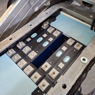
The batteries are positioned in their designated locations, and their fit is assessed to ensure secure mounting. It is important to check for accessibility, stability, and any potential conflicts with adjacent components.
The first step was to remove all of the fairing and tank to access the battery compartment, where the controls would be installed on top of the battery box.


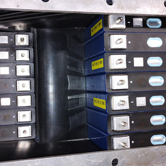
To begin, we must make sure that the batteries are kept from touching the sides of the box by placing rubber around them. This will help secure the batteries in place and ensure a proper and snug fit when they are installed in the battery compartment.
Below are photos of the progress of fitting in the rubber to protect the batteries from contact with the box. Fitting the batteries into position and installing a block to support the top row of batteries over the bottom row.
The battery suppliers at ELMOFO, use these batteries in multiple vehicle installations and advised me they are unlikely to expand, so they can be firmly fitted into the enclosure. The result should be a firm fit to minimise battery movement once the installation is completed and the lid is fixed into position.


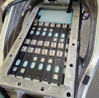
The Battery Management System (BMS) will be installed at the front of the battery compartment. I have attached the BMS to an HDPE board, which will serve both as a mount for the unit and to secure the bottom row of batteries in place.


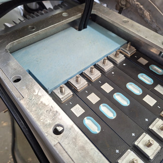
Next, I have cut two pieces of HDPE Board that will be joined and placed inside the box to prevent the top row of batteries from moving forward and upward once they are installed and secured in place.


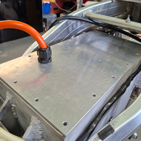
The negative output from the BMS will exit at the top front of the battery box. After considerable deliberation, it was decided that the positive cable will also exit from the top, but closer to the rear of the battery pack.
As I need a sharp bend on the 50mm orange cable, it is best to put the bend into the cable before crimping on the lug, as the strands of wire move within the cable when bent, then the cable will maintain the shape once the lug is crimped on.


The placement of the control components on the top of the box will be limited by the length of the motor cables.
After positioning and wiring the components, I can secure all of them to the top of the battery box lid. I have used two strips of aluminum to hold the Motor Controller in place and prevent it from shifting.


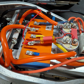
In the video below, I'll strive to explain how the power circuit functions.
Since we are confident that everything fits on and in the structure and I'm satisfied with the layout, the next step is to take off the controls and batteries from the bike, remove the box, frame, and motor, and prepare it for painting.


Comments